

Frequently Asked Questions
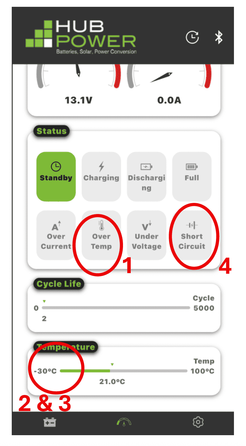
Check the APP to see if the BMS has shut down the battery due to:
- High temperature setting limit has being exceeded. If the high temperature setting is exceeded, 60C or 140F, you need to cool the battery down below 60C or 140F to charge the battery.
- Low temperature limit has been exceeded. Battery is below 0C or 32F, check temperature sensor reading. When the battery is below the cold temperature charging threshold, the charge applied by the charger will go to the heater mat to heat the cells above 0C. Once the battery cells are above 0C or 32F, the cells/battery will start taking a charge.
- Faulty Temperature Sensor, if the temperature sensor shows below -20C (usually -40C) and the ambient temperature is above 0C.
- Short Circuit – A short circuit has occurred in the battery. Please call Hub Power for assistance, 604-420-7737 or e-mail sales@hubpower.ca.
- Is your battery charger on and working? If no, turn battery charger on and charge your batteries.
- Check to make sure that the charger is properly connected to the battery and all wiring connections are secure. Loose connections can cause voltage drops and the inability to provide the battery with a charge.
You can find the HubPower Lithium Battery APPs at the following links:
Hub Power Android Phone App – Android/Google App Store: https://play.google.com/store/apps/details?id=com.yep.hub_power&hl=en_CA
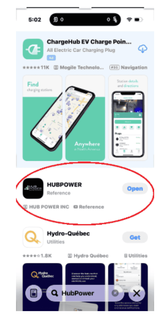
Hub Power iPhone App – Apple App Store: https://apps.apple.com/ca/app/hubpower/id6752604509
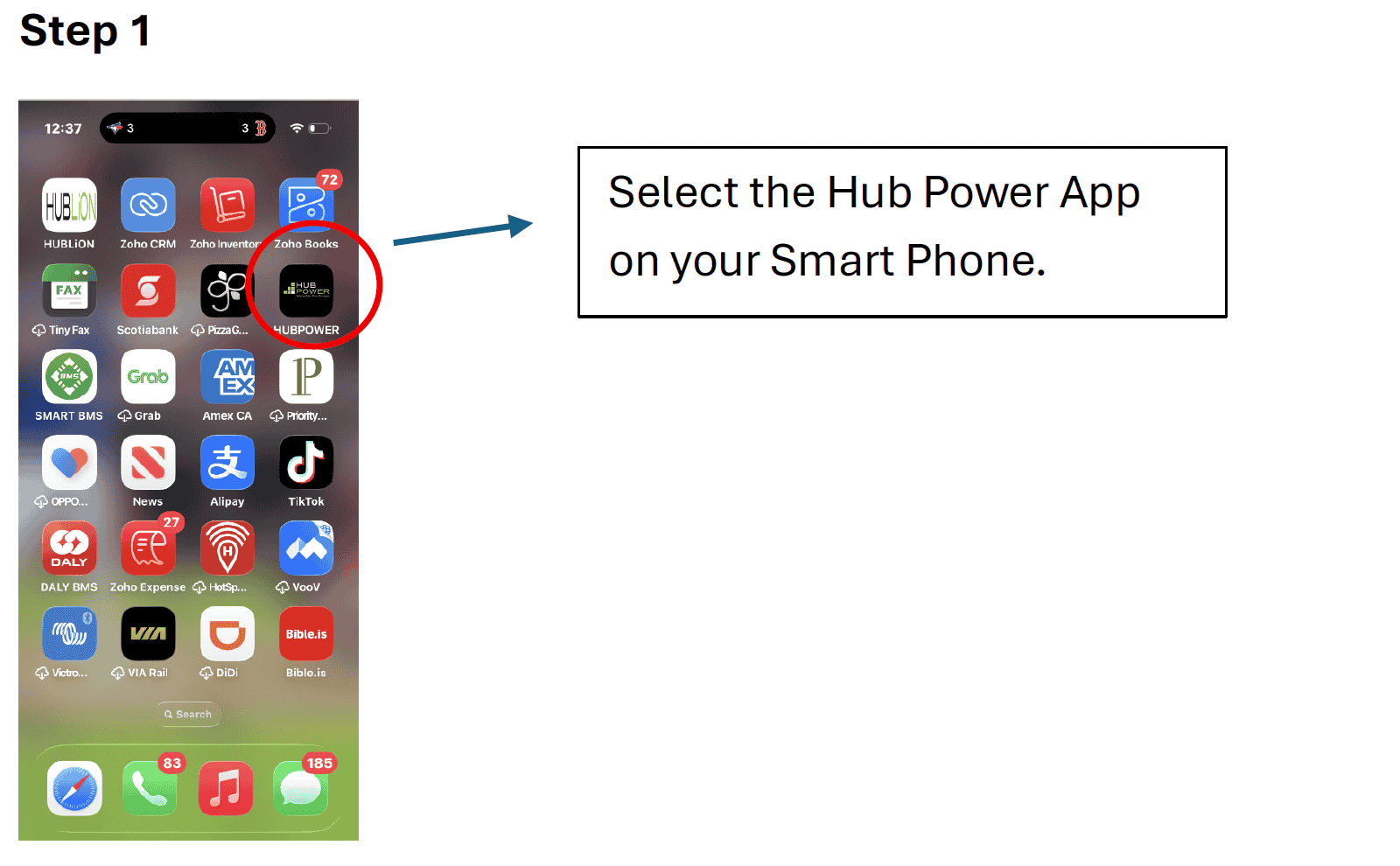
Look for the HubPower Icon:
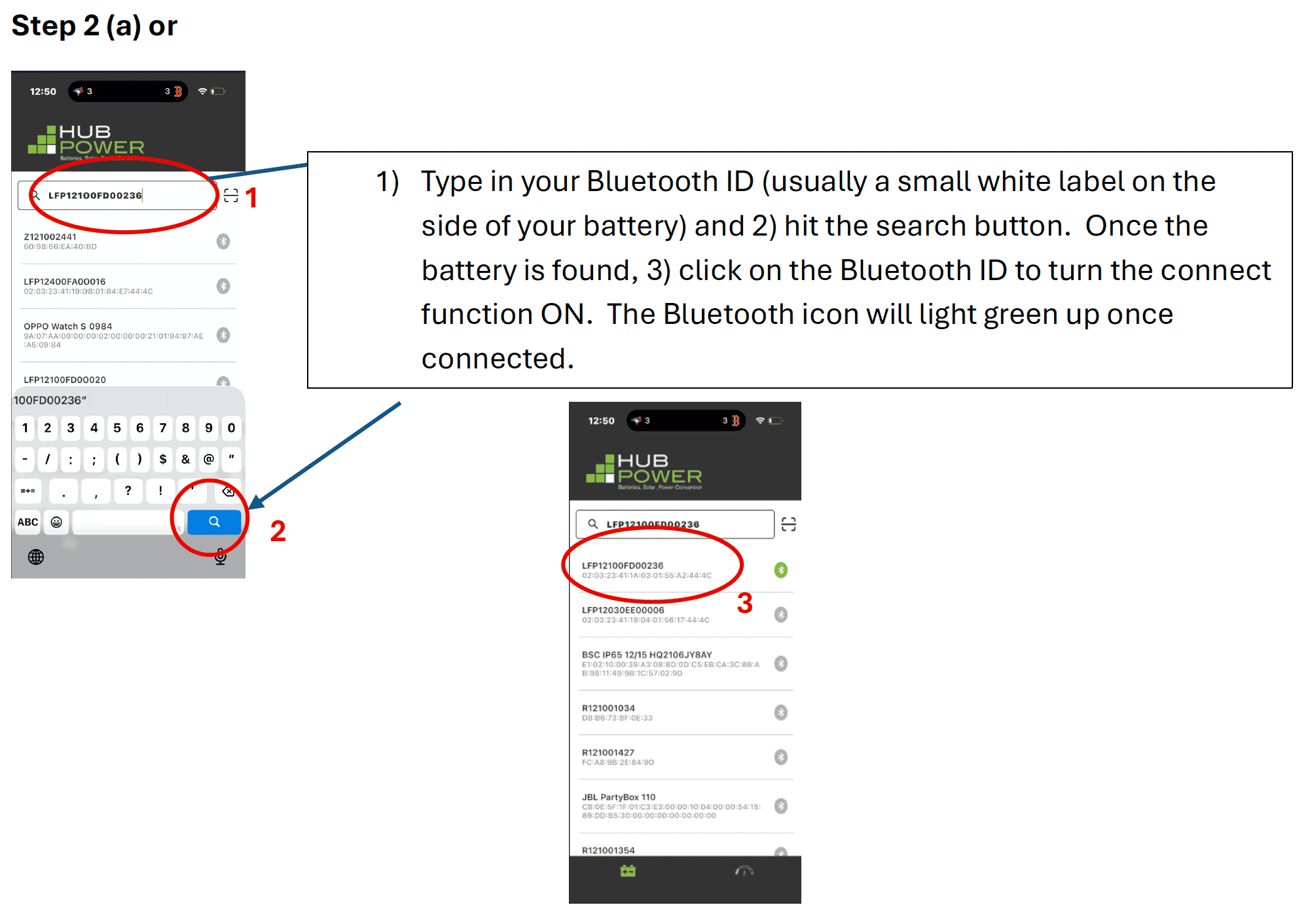
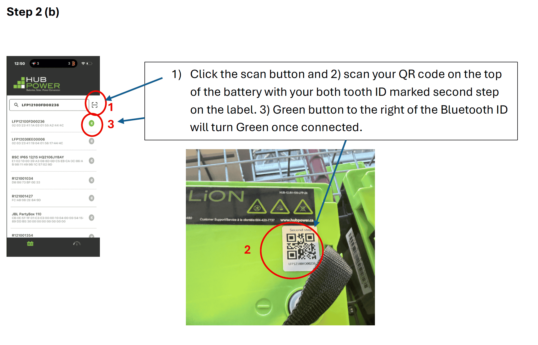
If you have multiple batteries in your system, you need to repeat Step 2 until you have connected to all of them via Bluetooth. The Bluetooth icons to the right of the Bluetooth ID will be highlighted in green.
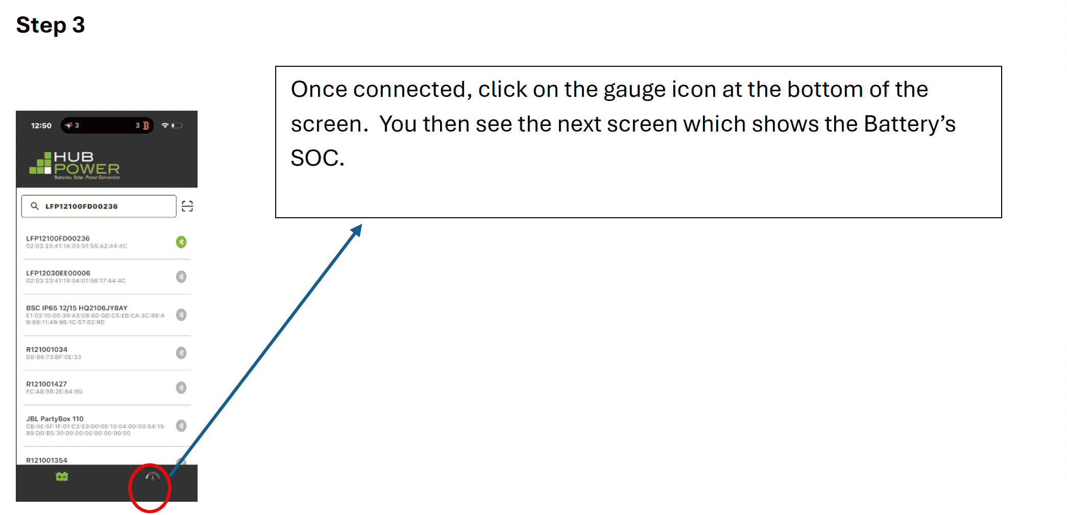
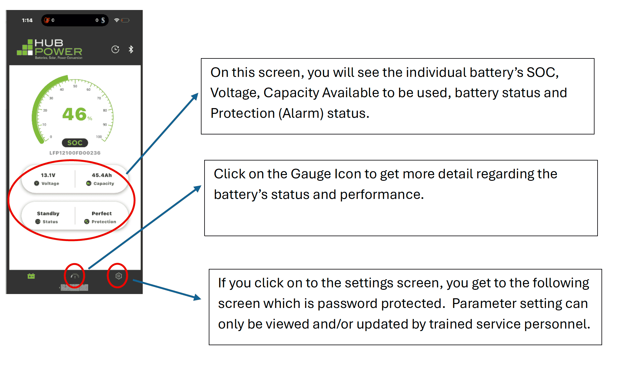
Once you have connected to your battery (see the FAQ regarding connecting to the Battery once HubPower APP has been downloaded), you will see the first main screen.
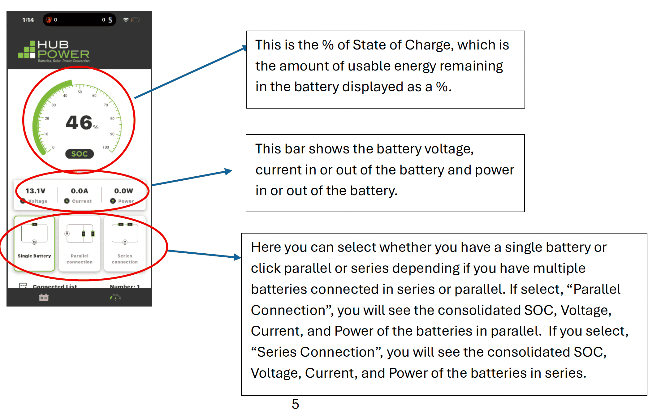
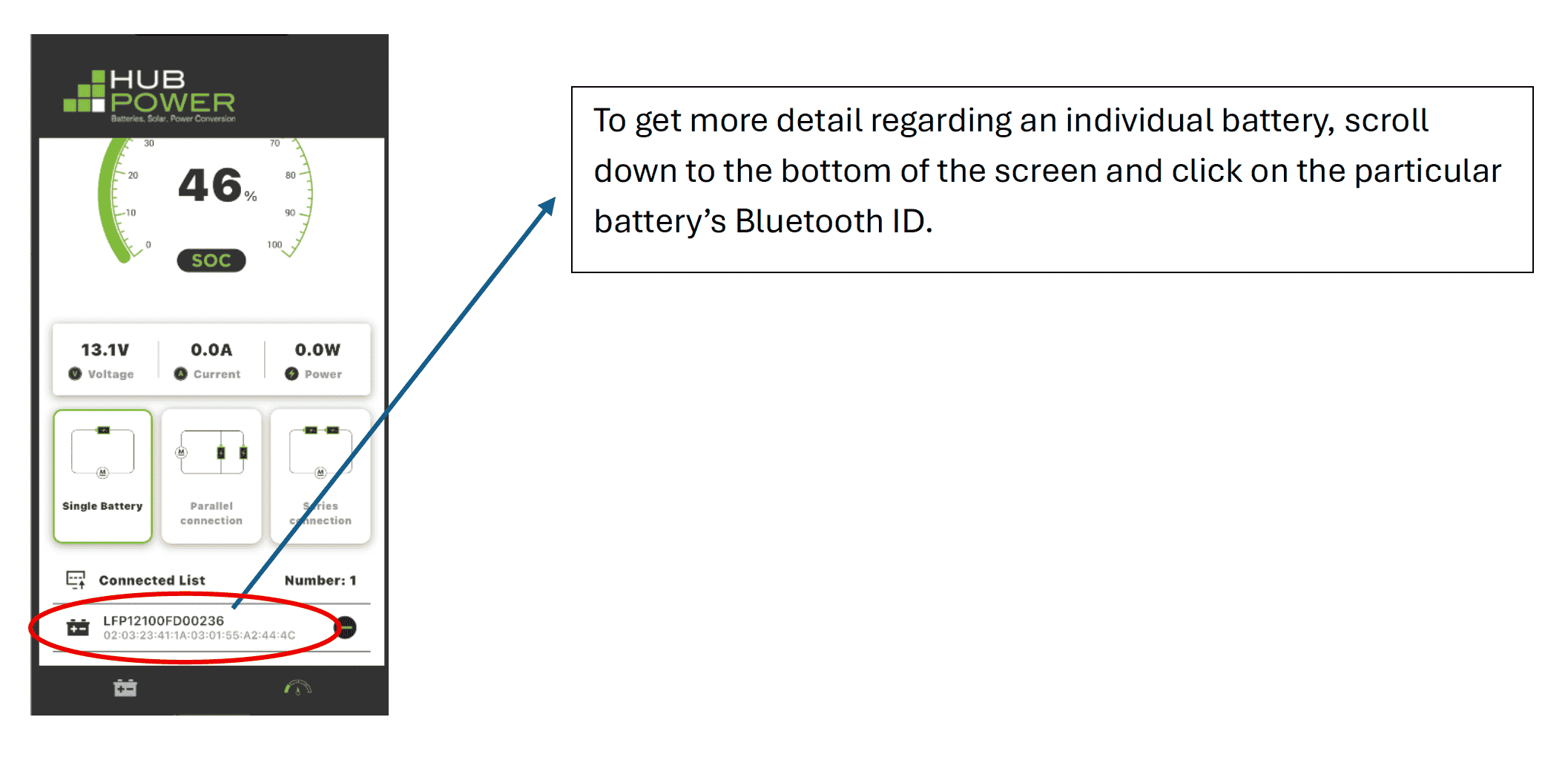
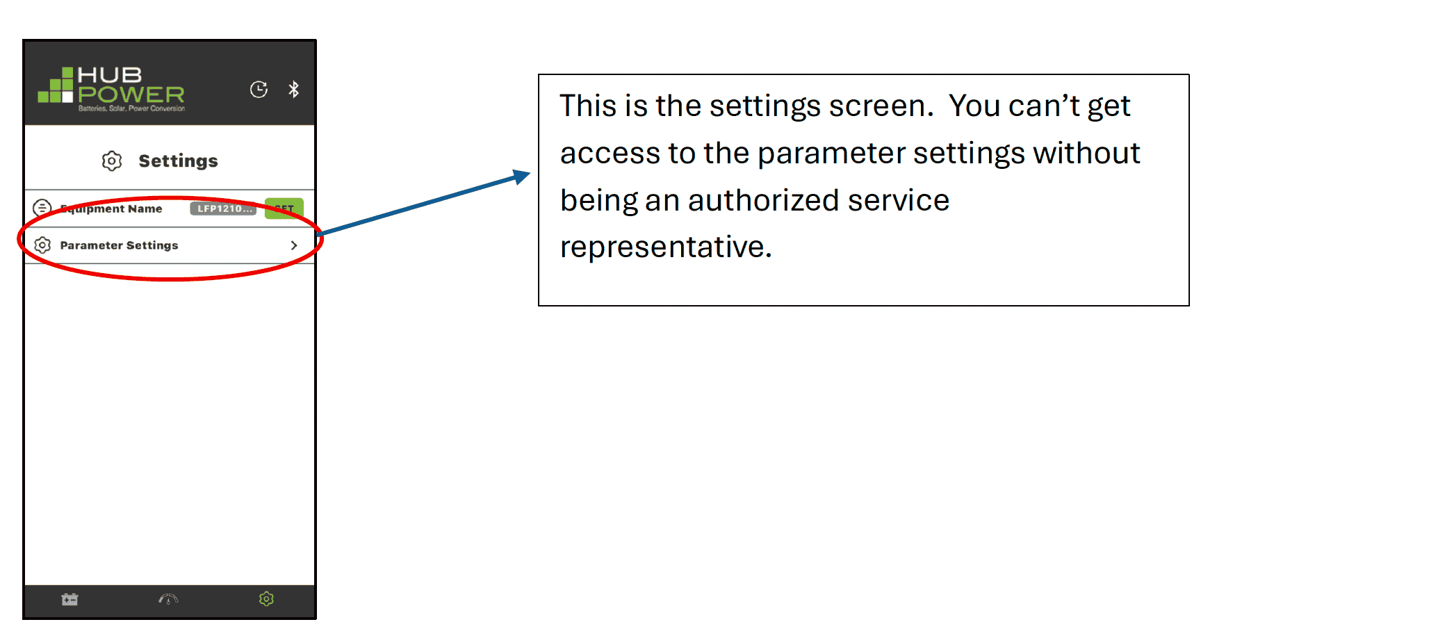
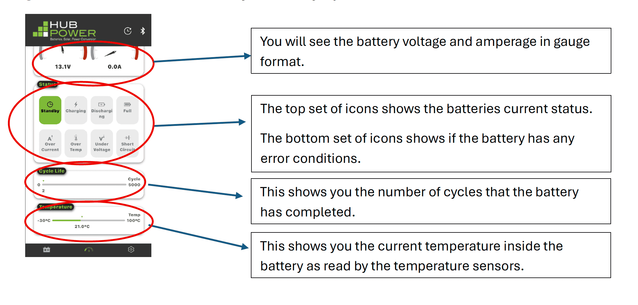
Once you click on the gauge icon, you will see this next screen. On this screen you will get to see a more detailed view of your battery’s performance status.
HUBLiON Lithium Battery Winter Storage Procedure
Long-Term Storage & Winterization Guidelines
Before Storage
Charge battery to 50–70% SOC. Avoid storing at 100% or below 20% SOC. Disconnect all loads, chargers, solar charge controllers, and eliminate parasitic loads. Inspect terminals, connections, and battery condition.
Recommended Storage Environment
Store in a clean, dry indoor location. Ideal storage temperature is 10°C to 25°C (50°F to 77°F). Acceptable range is -10°C to 35°C (14°F to 95°F). Maintain less than 75% relative humidity.
During Storage
Inspect every 3 months. Check state of charge and recharge if SOC falls below 40–50%. Return battery to approximately 50–70% SOC after charging.
Cold Weather Considerations
Do not charge below the battery’s minimum charging temperature, 0C or 32F. Charge applied below 0C will activate the heater mat. The battery will not charge until the heater mat warms the battery above 0C (32F). The Heater Mat shuts off at 5C.
Returning the Battery to Service
Inspect the battery, verify all connections, fully charge to 100%, reconnect equipment, and confirm proper operation.
Safety Information
Use approved lithium chargers only. Do not short-circuit, disassemble, modify, or expose the battery to fire or excessive heat.
Storage Summary
Ideal Storage SOC: 50–70%. Recharge Threshold: 40–50%. Inspection Interval: Every 3 Months. Maximum Storage Duration: Up to 12 Months.
Long-Term Storage & Winterization Guidelines for AGM Batteries
Before Storage
Fully charge all AGM batteries. Disconnect shore power and all parasitic loads. Inspect and clean terminals and connections.
Recommended Storage Conditions
Store fully charged batteries in a cool, dry, ventilated location. Recommended temperature: 0°C to 25°C (32°F to 77°F).
During Storage
Inspect monthly. Recharge if battery voltage drops below 12.5V. Recharge every 60–90 days if no maintainer is connected.
Battery Maintainers
Use an AGM-compatible smart charger with float mode and temperature compensation.
Cold Weather Considerations
Always store AGM batteries fully charged to prevent freezing damage and sulfation.
Returning the AGM Batteries to Service
Inspect, clean, fully charge, test under load, and reconnect all systems.
Safety Information
Use AGM-compatible chargers only. Avoid sparks, flames, and short circuits. Ensure adequate ventilation when charging.
Storage Summary
100% SOC, monthly inspection, recharge below 12.5V, maintenance charge every 60–90 days.
| Battery Comparison Guide | ||||
|---|---|---|---|---|
| Feature / Type | Flooded (FLA) | AGM (Sealed) | Lead Carbon | Lithium (LiFePO4) |
| Upfront Cost | Low | Medium | Medium-High | High |
| Maintenance | High (watering required) | None | None | None |
| Cycle Life | Low (300–500 cycles) | Medium (500–800 cycles) | High (1000–1500 cycles) | Very High (3000–5000+) |
| Weight | Heavy | Heavy | Heavy | Lightweight |
| Depth of Discharge | ~50% usable | ~50–60% usable | ~70% usable | ~90–100% usable |
| Charging Speed | Slow | Moderate | Faster than AGM | Very Fast |
| Performance in Cold | Good | Good | Good | Average when heated |
| Partial SOC Performance | Poor | Moderate | Excellent | Excellent |
| Lifespan (Years) | 2–4 | 3–5 | 4–7 | 8–15+ |
| Best For | Budget / occasional use | General RV use | Frequent off-grid / solar use | Full-time / high-performance RV |
How Does a Solar Panel Work?
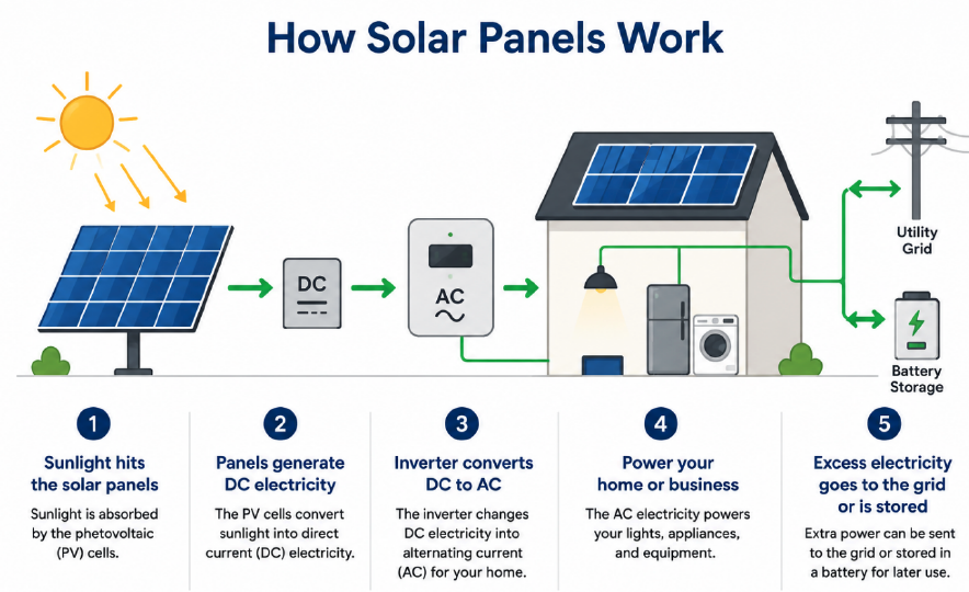
Solar panels convert sunlight into electricity using photovoltaic (PV) cells. When sunlight shines on these cells, it energizes electrons within the panel’s semiconductor material, creating an electric current.
Here’s a simple breakdown of the process:
- Sunlight hits the solar panels mounted on your RV, Boat, Work Truck, roof or property.
- Photovoltaic cells generate direct current (DC) electricity from the sun’s energy.
- An inverter converts the DC electricity into alternating current (AC), which is the type of electricity used in RVs, boats, work trucks, homes and businesses.
- Your vehicle, home or business uses the solar-generated electricity to power lights, appliances, and equipment.
- Any excess electricity can often be sent back to the electrical grid (grid tie system) or stored in a battery system for later use.
Solar panels produce electricity whenever they receive daylight, even on cloudy days, although output is highest in direct sunlight. Because solar energy comes from the sun, it is a clean, renewable source of power that can help reduce electricity costs and lower carbon emissions.
Why Do Solar Panels Degrade Over Time?
Solar panels are designed to last for decades, but like any product exposed to the elements, they gradually lose some efficiency over time. This process is known as solar panel degradation.
The most common causes include:
- Exposure to sunlight (UV radiation): Constant exposure to the sun slowly breaks down the materials within the panel.
- Temperature changes: Daily heating and cooling cause the panel materials to expand and contract, creating minor stress over many years.
- Weather exposure: Rain, snow, wind, hail, and humidity can gradually wear on the panel’s protective components.
- Moisture intrusion: Although panels are sealed, small amounts of moisture can sometimes penetrate over time and affect internal components.
- Microcracks: Tiny cracks can develop in solar cells due to thermal stress, wind loading, or handling during installation.
- Material aging: Electrical connections, sealants, and backing materials naturally age and become less effective over time.
Most modern solar panels degrade at a relatively slow rate of about 0.25% to 0.75% per year. As a result, many panels still produce 80% to 90% of their original output after 25 years, which is why manufacturers commonly offer 20-year performance warranties.
Expanding your RV solar system can help you spend more time off-grid, but the best upgrade depends on your power needs and your existing equipment.
- Start by Understanding Your Power Usage
Before adding more solar panels, consider:
- How much power you use each day.
- Whether you’ve added new loads such as a larger refrigerator, Starlink, air conditioning, induction cooking, or additional electronics.
- How often you camp without shore power or a generator.
Knowing your daily energy consumption helps determine whether you need more solar panels, more battery storage, or both.
- Check Your Existing System Components
To keep costs down, determine whether your current equipment can support additional solar panels:
- Solar charge controller capacity.
- Battery bank size and type (lead-acid or lithium).
- Inverter capacity.
- Available roof space and mounting options.
Sometimes the most expensive part of an expansion is upgrading a charge controller that has already reached its maximum solar input.
- Match New Panels to Your Existing System
For the simplest and most economical expansion:
- Choose panels with similar voltage and electrical characteristics to your existing panels.
- Avoid mixing significantly different panel sizes or technologies on the same charge controller when possible.
- Ensure the charge controller can handle the increased solar capacity.
Properly matched panels help maximize energy production and prevent losses.
- Consider Portable Solar Panels
If roof space is limited, portable solar panels can be a cost-effective solution:
- No roof modifications required.
- Can be positioned in direct sunlight while the RV stays in the shade.
- Easy to add to many existing solar systems.
Portable panels are often one of the most affordable ways to increase solar production.
- Don’t Forget Battery Storage
Many RV owners discover that their batteries are the limiting factor—not their solar panels.
If your batteries are fully charged by midday but you still run out of power overnight, upgrading your battery bank may provide more benefit than adding additional solar panels.
- Plan for Future Upgrades
If you expect your power needs to grow, consider installing equipment that allows for future expansion, such as:
- Larger MPPT charge controllers.
- Additional battery capacity.
- Higher-capacity inverters.
Planning ahead can save money by avoiding multiple equipment replacements.
When solar panels with different specifications are connected together, the system usually performs based on the weakest matching electrical value.
In series:
Voltages add together, but the current is limited by the lowest-current panel.
Example:
Panel A: 20V, 5A = 100W
Panel B: 20V, 8A = 160W
Connected in series:
20V + 20V = 40V
Current limited to 5A
Estimated output = 40V × 5A = 200W
Even though the panels are rated for 260W total, the mismatch reduces usable power.
In parallel:
Currents add together, but the voltage is pulled toward the lower-voltage panel.
Example:
Panel A: 20V, 5A = 100W
Panel B: 18V, 8A = 144W
Connected in parallel:
Voltage operates near 18V
Current = 5A + 8A = 13A
Estimated output = 18V × 13A = 234W
How to Estimate New Output
Use these simplified formulas:
Series connection:
Total watts ≈ total voltage × lowest panel current
Parallel connection:
Total watts ≈ lowest panel voltage × total current
Best Practice for RV Solar
For the best performance and lowest cost, try to match panels with similar:
- Voltage
- Current
- Wattage
- Cell type
- Age and condition
For mixed panels, it is often better to use a separate MPPT charge controller for the new panels, especially if the new panels are much larger, newer, or different from the existing ones.
BMS – SOC mis-calibration
Over time, it is common for a lithium battery’s built-in BMS to become inaccurate, where it displays a % State-of-charge (SOC) that is different than what is actually in its cells. This can be caused by a number of normal factors such as:
- Coulomb counting errors / margin of measuring accuracy
- Cell age & condition
- Temperature-related effects on capacity
- Self-discharge (internal within the cells)
Fortunately, it is very easy to re-calibrate the BMS so that it once again displays an accurate SOC. To do so, follow these steps:
- Warm battery to room temperature (if cold)
- Charge the battery fully using a compatible lithium battery charger until internal voltage of 14.4 to 14.6V is achieved (bulk and absorption charge should be set between 14.4 and 14.6V.)
Once the battery has been completely discharged and recharged using the steps above, the SOC displayed by the BMS should read close-to, or at 100%.
Multi-battery installations – SOC’s are not the same across all my batteries
It is normal, under certain circumstances, for lithium batteries within a battery bank to display different SOC’s. The reasons can include:
- Battery bank contains batteries of different ages, condition, capacities, models, or brands
- SOC mis-calibration (as noted above in BMS – SOC mis-calibration)
- Differences in wiring and connection resistance throughout the battery array Temperature differences across a battery array (especially when internal heating is activated)
The procedure to re-calibrate the batteries and BMS’s is the same as before, and ideally should be done to each battery individually.
- Warm each battery to room temperature (if cold)
- Charge the battery fully using a compatible lithium battery charger until internal voltage of 14.4 to 14.6V is achieved (bulk and absorption charge should be set between 14.4 and 14.6V.)
| Battery Model | Battery Voltage | Bulk Charge | Absorption Charge | Float Charge |
|---|---|---|---|---|
| HUB AGM | 6V | 7.3V | 7.3V | 6.85V |
| HUB AGM | 12V | 14.7V | 14.7V | 13.6V |
| HUB CARBON | 6V | 7.3V | 7.3V | 6.85V |
| HUB CARBON | 8V | 9.73V | 9.73V | 9.13V |
| HUB CARBON | 12V | 14.6V | 14.6V | 13.7V |
| HUB LION | 12V | 14.4V | 14.6V | 14.0V |
| HUB LION | 24V | 28.8V | 29.2V | 28.6V |
| HUB LION | 51V | 56.8V | 58.4V | 57.6V |
If you’re configuring a Victron MultiPlus or MultiPlus-II charger/inverter, these are some of the best step-by-step videos available:
- Complete MultiPlus Programming Walkthrough (Recommended for Multiplus Owners)
How to Program a Victron MultiPlus/Quattro Inverter Charger
- Covers charger settings, battery profiles, charge current limits, inverter settings, and common RV/off-grid configurations.
- Excellent beginner-to-intermediate tutorial.
- Link: Watch on YouTube
- Particularly useful if you’re using lithium batteries in an RV.
- Victron MultiPlus Programming – Step-by-Step
How-To: Program a Victron MultiPlus Inverter Charger
- A practical setup guide showing how to connect and configure the MultiPlus using VEConfigure software.
- Link: Watch on YouTube
- Good for first-time installations and lithium battery systems.
- VEConfigure Settings Deep Dive
Victron VEConfig – Grid Settings Tab Tutorial
- Detailed explanation of AC input limits, transfer switch settings, UPS mode, and generator/grid configuration.
- Link: Watch on YouTube
- Especially helpful if you use shore power, generators, or have nuisance transfer issues.
- Understanding How the MultiPlus Works
Inside the Victron MultiPlus & a Detailed Explanation of How It Works
- Not a programming video, but one of the best explanations of what the charger/inverter is actually doing.
- Link: Watch on YouTube
- Helps make sense of settings such as PowerAssist, charger current limits, and inverter behavior.
- Victron’s Official Documentation
If you want to verify charger settings for your specific battery:
- Charger Settings Manual: Victron VEConfigure Charger Settings
- MultiPlus Configuration Manual: Victron MultiPlus-II Configuration Guide
For Owners Using Lithium Batteries
The most important settings to verify are:
- Absorption voltage
- Float voltage
- Maximum charge current
- AC input current limit (shore power limit)
- PowerAssist settings
- Battery temperature compensation (usually disabled for lithium batteries if the battery manufacturer recommends it)
- Low Voltage Cut off reached. If the battery reaches its low voltage limit, it will shut off the battery. You need to apply a charge to the battery and increase the battery voltage to .4V above the low voltage cut off for the battery. Once that threshold is reached the battery will resume discharging.
- Battery SOC reaches 0% – you need to charge your battery immediately once the SOC cut of limit is reached.
- Loads are cutting out when battery is at a lower SOC. Battery doesn’t have enough energy to support the loads so you need to charge it in order to have adequate energy or turn off non-critical loads.
For optimal battery life, it recommended to charge your batteries when the SOC reaches 20%.
- You may have over-currented the battery. Check the lithium APP for an over-current warning. If there is a warning, either turn off loads or charge the battery to get more energy.
- Check to see if an AC breaker, DC breaker or GFCI breaker has tripped. If yes, reset AC breaker, DC breaker, or GFCI.
- You may have blown the battery fuse. Use a multi-meter to check the voltage at the battery terminals. If the voltage is above 12.3V, the battery is in operating range. Check the voltage after the battery fuse to see if it also has voltage output. If voltage is 0V, replace fuse.
- Low Voltage Cut off reached. If the battery reaches its low voltage limit, it will shut off the battery. You need to apply a charge to the battery and increase the battery voltage to .4V above the low voltage cut off for the battery. Once that threshold is reached the battery will resume discharging.
- Check your inverter or inverter-charger to make sure that it is on or is not in an error mode. Consult your inverter manual for troubleshooting.
Lead-acid batteries are reliable and cost-effective, but their lifespan can be significantly reduced by improper charging, excessive discharge, and poor maintenance.
The most common causes of premature battery failure include:
- Deep Discharging
Repeatedly discharging a lead-acid battery below 50% of its capacity can shorten its lifespan. The deeper the discharge, the fewer charge cycles the battery will typically provide.
- Sulfation
When a battery remains partially discharged for extended periods, lead sulfate crystals can harden on the battery plates. This process, called sulfation, reduces the battery’s ability to accept and hold a charge and is one of the leading causes of battery failure.
- Overcharging
Excessive charging voltage can cause overheating, excessive water loss, plate corrosion, and permanent damage to the battery’s internal components.
- Undercharging
Consistently failing to fully recharge a battery can lead to sulfation and reduced capacity over time.
- High Temperatures
Heat accelerates chemical reactions inside the battery, increasing corrosion and water loss. Prolonged exposure to high temperatures can significantly shorten battery life.
- Low Electrolyte Levels
In flooded lead-acid batteries, low electrolyte levels expose the plates to air, causing irreversible damage. Regular inspection and maintenance are important to maintain proper electrolyte levels.
- Vibration and Physical Damage
Excessive vibration, shock, or poor mounting can damage internal battery components and connections, particularly in RV, marine, and off-road applications.
- Corroded or Loose Connections
Dirty, corroded, or loose battery terminals can increase resistance, reduce charging efficiency, and lead to poor battery performance.
- Long-Term Storage Without Charging
Lead-acid batteries naturally self-discharge over time. Batteries left in storage without periodic charging can become deeply discharged, and suffer permanent capacity loss.
Proper charging, avoiding deep discharges, and regular maintenance can significantly extend battery life.
It depends on the amount of current being drawn from the battery. You can use the following table as a starting point.
| PART NOS | DISCHARGE RATE | FV | DISCHARGE TIME IN MINS |
DISCHARGE TIME IN MINS @ 10.5V CUT-OFF (HP VERS) |
NOTES |
|---|---|---|---|---|---|
| HUB LEAD CARBON | |||||
| HC6-220 | 75A | 10.5 | 120 | 117 | discharge in pairs (6V x 2) |
| HC6-240 | 75A | 10.5 | 150 | 146 | discharge in pairs (6V x 2) |
| HC6-420 | 75A | 10.5 | 240 | 247 | discharge in pairs (6V x 2) |
| HC12-75 | 75A | 10.5 | 25 | 24 | |
| HC12-100 | 75A | 10.5 | 35 | 32 | |
| HC12-115 | 75A | 10.5 | 40 | 37 | |
| HC12-140 | 75A | 10.5 | 45 | 44 | |
| HC12-250 | 75A | 10.5 | 150 | 137 | |
| HUB AGM | |||||
| HBGC2-220 | 75A | 10.5 | 120 | 110 | discharge in pairs (6V x 2) |
| HBL16-420 | 75A | 10.5 | 240 | 233 | discharge in pairs (6V x 2) |
| HB27-100 | 75A | 10.5 | 35 | 32 | |
| HB31-120 | 75A | 10.5 | 40 | 37 | |
| HBGC2-170 | 75A | 10.5 | 90 | 82 | |
| HB8D-260 | 75A | 10.5 | 120 | 117 | |
| HB4D-200 | 75A | 10.5 | 90 | 87 | |
To size a battery, add up how much power your devices use and how long you want to run them.
Step 1: List Your Loads
For each device, find:
Watts × hours used per day = watt-hours per day
Example:
| Load | Watts | Hours Used | Energy Used |
| LED lights | 20W | 5 hrs | 100Wh |
| Fridge | 60W | 10 hrs | 600Wh |
| Fan | 40W | 6 hrs | 240Wh |
Total daily use:
100Wh + 600Wh + 240Wh = 940Wh per day
Step 2: Convert Watt-Hours to Battery Amp-Hours
Use this formula:
Battery Ah needed = watt-hours ÷ battery voltage
Example for a 12V system:
940Wh ÷ 12V = 78Ah
Step 3: Add Extra Capacity for Battery Type
You should not use 100% of most batteries.
Typical usable capacity:
| Battery Type | Recommended Usable Capacity |
| Flooded lead-acid | ~50% |
| AGM lead-acid | ~50% |
| Lithium LiFePO₄ | ~80–90% |
Example using lead-acid:
78Ah ÷ 50% = 156Ah battery bank
Example using lithium:
78Ah ÷ 80% = 98Ah battery bank
Step 4: Add a Safety Margin
Add 20–30% extra capacity for cloudy days, colder weather, inverter losses, and future loads.
To size solar for an RV or boat, first calculate how much energy you use each day, then choose enough solar panel capacity to replace that energy during daylight hours.
Step 1: Calculate Your Daily Energy Use
List each electrical load and estimate how long it runs per day:
Watts × hours used per day = watt-hours per day
Example:
| Load | Watts | Hours/Day | Daily Use |
| Lights | 20W | 5 hrs | 100Wh |
| Fridge | 60W | 12 hrs | 720Wh |
| Water pump | 80W | 0.5 hrs | 40Wh |
| Laptop | 65W | 3 hrs | 195Wh |
Total daily use: 1,055Wh per day
Step 2: Adjust for System Losses
Solar systems lose some energy through wiring, charge controllers, heat, shading, and battery charging.
A simple estimate is:
Daily energy use ÷ 0.75 = solar energy needed
Example:
1,055Wh ÷ 0.75 = 1,407Wh per day
Step 3: Estimate Your Available Sun Hours
Use your average “peak sun hours” per day. Many RV and boat systems use 3–5 peak sun hours as a planning estimate.
Step 4: Calculate Solar Panel Size
Solar watts needed = adjusted daily watt-hours ÷ peak sun hours
Example using 4 peak sun hours:
1,407Wh ÷ 4 = 352W
In this example, a 400W solar array would be a practical minimum.
Step 5: Add a Safety Margin
Add 20–30% extra solar capacity for cloudy weather, panel angle, partial shade, and future loads.
For the example above:
352W × 1.25 = 440W
A good recommendation would be 400–500W of solar panels.
RV and Boat Considerations
For RVs and boats, solar output can vary because of:
- Roof space limitations
- Shade from vents, antennas, trees, sails, or rigging
- Flat-mounted panels
- Changing location and weather
- Battery size and charge controller limits
Both glass and flexible solar panels convert sunlight into electricity, but they are designed for different applications and environments.
Glass Solar Panels
Traditional solar panels use solar cells protected by tempered glass and mounted within a rigid aluminum frame.
Advantages:
- Higher efficiency and power output.
- Longer lifespan (typically 25+ years).
- Better resistance to weather, UV exposure, and environmental wear.
- Usually backed by longer manufacturer warranties.
- Lower cost per watt over their lifetime.
Considerations:
- Heavier than flexible panels.
- Require a rigid mounting surface.
- Less suitable for curved surfaces.
Best For:
- RV roofs with adequate structural support.
- Boats with rigid mounting locations.
- Cabins, homes, and off-grid installations.
- Applications where maximum power production and longevity are priorities.
Flexible Solar Panels
Flexible panels use thin, lightweight materials that allow them to bend and conform to curved surfaces.
Advantages:
- Lightweight and low-profile.
- Can be mounted on curved or irregular surfaces.
- Easier installation in some applications.
- Ideal where weight is a critical factor.
Considerations:
- Generally lower efficiency than glass panels.
- More susceptible to heat buildup, which can reduce performance.
- Shorter lifespan in many applications.
- Typically shorter warranty periods.
- Higher cost per watt over their service life.
Best For:
- Curved RV roofs.
- Sailboats and marine applications with limited mounting options.
- Portable solar systems.
- Applications where weight and flexibility are more important than maximum output and longevity.
Which Is Better?
For most RV and marine owners, glass solar panels are the preferred choice when space and mounting options allow. They typically provide:
- More power from the same roof area.
- Better long-term reliability.
- Lower lifetime cost.
- Longer warranties.
Flexible panels are often the best solution when:
- Weight must be minimized.
- The mounting surface is curved.
- Traditional framed panels cannot be installed.
A solar charge controller regulates the power flowing from your solar panels to your batteries. The two most common types are PWM (Pulse Width Modulation) and MPPT (Maximum Power Point Tracking) controllers.
While both can charge batteries safely, they operate very differently and can significantly affect the performance of your solar system.
PWM (Pulse Width Modulation) Charge Controllers
PWM controllers connect the solar panel directly to the battery and regulate charging by rapidly switching the current on and off.
Advantages:
- Lower upfront cost.
- Simple and reliable design.
- Suitable for small solar systems.
- Works well when panel voltage closely matches battery voltage.
Considerations:
- Less efficient than MPPT controllers.
- Excess panel voltage is lost and cannot be converted into additional charging power.
- Performance decreases in cold weather or when using higher-voltage solar panels.
Best For:
- Small RV, boat, or cabin systems.
- Budget-conscious installations.
- Systems under approximately 200 watts.
MPPT (Maximum Power Point Tracking) Charge Controllers
MPPT controllers continuously track the solar panel’s maximum power point and convert excess voltage into additional charging current.
This allows the controller to harvest more energy from the solar panels.
Advantages:
- Typically 15–30% more efficient than PWM.
- Converts excess panel voltage into usable battery charging current.
- Performs better in cold temperatures and variable weather conditions.
- Allows higher-voltage solar arrays, reducing wire size and voltage drop.
- Ideal for larger solar systems.
Considerations:
- Higher purchase price.
- More complex electronics.
Best For:
- RV and marine systems.
- Larger battery banks.
- Lithium battery systems.
- Installations where maximizing solar production is important.
Example
Suppose you have a solar panel rated at:
- 200 Watts
- 20 Volts
- 10 Amps
Charging a 12V battery:
PWM Controller
- Operates near battery voltage (approximately 13–14V)
- Power delivered ≈ 140W
MPPT Controller
- Converts excess voltage into additional current
- Power delivered ≈ 190–200W (minus small conversion losses)
In this example, the MPPT controller can deliver significantly more charging power from the same panel.
Which Is Better?
For most modern RV, boat, and off-grid systems, MPPT charge controllers are the preferred choice because they:
- Produce more energy from the same solar panels.
- Work better with lithium batteries.
- Support larger solar arrays.
- Improve charging performance during less-than-ideal conditions.
PWM controllers remain a practical option for very small systems where minimizing cost is more important than maximizing energy production.
Have more questions?
Contact Hub Power today
👉 Email: sales@hubpower.ca
👉 Talk to an Expert: 604-420-7737